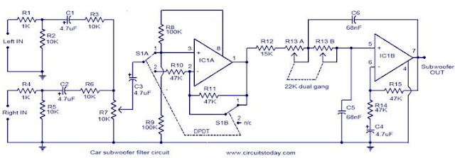
Here is the circuit diagram of a simple subwoofer filter that can
be operated from a 12V DC supply. Such a circuit is very useful in automobile subwoofer
applications. The circuit is nothing but a low pass filter whose pass frequency
can be adjusted between 60 to 160 Hz.
The circuit is designed around the TL072 dual BIFET opamp IC. Out of the two
opamps inside the chip, IC1A is wired as a buffer. The left and right audio
inputs after mixing is fed to the input of the IC1A using the DPDT switch S1.
Switch S1 is the phase control switch which can be used to make the subwoofer
in phase with other speakers. When S1 is in position 2, 180 degree phase shift
will be induced.POT R7 can be used for controlling the level. IC1B forms the
low pass filter whose pass frequency can be controlled by adjusting the dual
gang POT R13.
Circuit diagram .
Notes.
- Assemble the circuit on a good quality PCB.
- The circuit can be powered from 12V DC.
- IC1 must be mounted on a holder.
- S1 is a DPDT switch.
- R13 should be a dual gang linear POT.
- C5 and C6 must be polyester capacitors.
- POT R13 can be used for adjusting the pass frequency.
- POT R7 can be used for adjusting the level
Itulah tadi Artikel Car subwoofer filter
Semoga artikel Car subwoofer filter yang saya bagikan kali ini, mudah-mudahan bisa memberi manfaat buat anda semua. Oke, sampai disini dulu yaaaah....Lain kali jumpa di postingan artikel berikutnya.
Oh ya... , sebelum anda meninggalkan halaman ini mungkin beberapa artikel yang sengaja kami pilihkan pada halaman di bawah ini juga tertarik untuk membacanya. Jika anda tidak sedang terburu buru saya akan merasa sangat bahagia jika anda berkenan mampir dulu pada beberapa artikel yang telah saya pilih kan dibawah ini.


